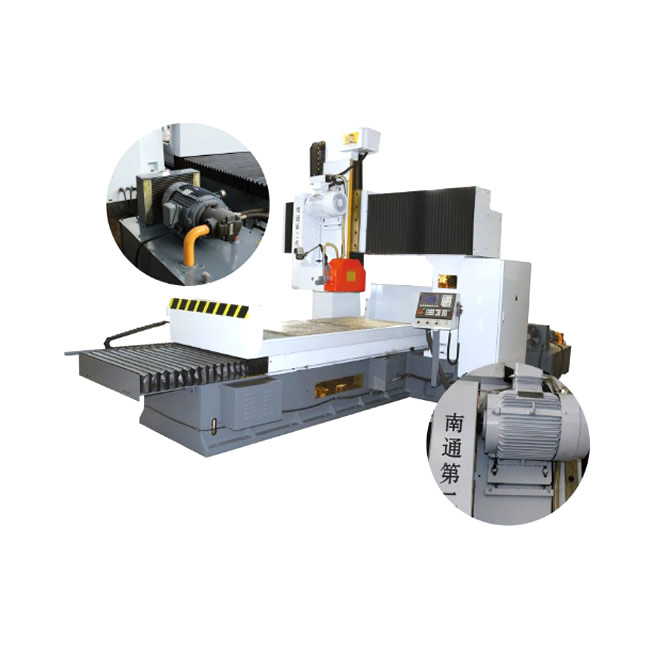
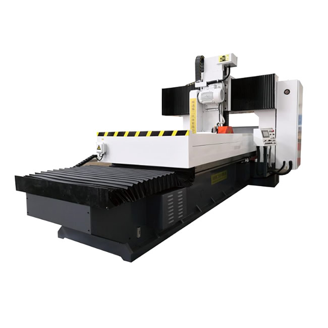
Main Purpose of the Machine
This is a general-purpose grinding machine that processes workpiece flat surfaces with the peripheral edge of the grinding wheel. According to different workpieces during grinding, the workpiece can be firmly adsorbed on the electromagnetic chuck, directly fixed on the worktable surface, or clamped on other fixtures.
It can grind workpieces made of steel, cast iron and non-ferrous metals. It is especially suitable for grinding large and medium-sized parts in machining workshops, measuring tool & mold factories and automobile industry.
The machine features compact structure, excellent performance, easy operation, flexible and reliable movement, stable precision, high rigidity, good thermal stability, low noise and convenient maintenance.
Main Features of the Machine
The machine adopts gantry structure. The columns and crossbeam are integrally cast, mounted on the bed to form a closed rigid frame. A slide carriage is fitted on the crossbeam, on which a ram is installed, and a horizontal wheelhead is mounted at the lower end of the ram. Driven by servo motors via timing belt pulleys and ball screws, the slide carriage moves left and right along the crossbeam (Y-axis) to realize cross feed of the wheelhead. The ram is driven up and down (Z-axis) by servo motors through reducers and ball screws for vertical wheelhead feed. The worktable is placed on the bed guideways, with two columns straddling above the table. Hydraulically driven, the worktable moves back and forth along the bed (X-axis) to complete longitudinal feed. The wheelhead adopts high-precision rolling bearing structure for stable rotation and superior surface finish of machined workpieces. (Both the hydraulic system and spindle bearings are purchased from well-known foreign brand manufacturers.)
Technical Parameters
| Item | Unit | MK2010 | MK20125 |
|---|
| Worktable Size (Width × Length) | mm | 1000×2000 | 1250×2000 |
| Max. Length of Ground Workpiece | mm | 2000 | 2000 |
| Max. Longitudinal Travel of Worktable | mm | 2100 | 2100 |
| Min. Longitudinal Travel of Worktable | mm | 200 | 200 |
| T-slots on Worktable (Qty × Width × Pitch) | mm | 5×22×200 | 5×22×200 |
| Worktable Speed (Stepless Speed Regulation) | m/min | 3‑25 | 3‑25 |
Distance from Grinding Wheel Spindle Center
to Worktable Surface | Max. (mm) | 860 | 860 |
| Min. (With Rear Water Guard Removed) (mm) | 180 | 180 |
| Max. Travel of Wheelhead | Cross (Manual or Motorized) (mm) | 1100 | 1340 |
| Vertical (Manual) (mm) | 680 | 680 |
| Vertical Feed Increment per Handwheel Pulse Division | mm | 0.01 | 0.01 |
| Grinding Wheel Specification (OD × ID × Width) | mm | 500X203X75 | 500X203X75 |
| Grinding Wheel Spindle Speed | r/min | 1400 | 1400 |
| Continuous Cross Movement Speed of Wheelhead | mm/min | 0‑10000 | 0‑10000 |
| Continuous Vertical Movement Speed of Wheelhead | mm/min | 0‑1500 | 0‑1500 |
| Wheelhead Motor Power | KW | 15 | 15 |
| Cross Feed Servo Motor Power | KW | 3.6 | 3.6 |
| Vertical Feed Servo Motor Power | KW | 3.6 | 3.6 |
| Main Oil Pump Motor Power | KW | 7.5 | 7.5 |
| Overall Dimension (L × W × H) | mm | 6200×3500×3600 | 6200×3600×3600 |
Machine Accessories
| 1 | Foundation Bolts + Nuts + Washers | 1 Set | 5 | Electromagnetic Chuck | 1 Set | 9 | Wheelhead Chuck Spanner | 1 Set |
| 2 | Leveling Pads | 1 Set | 6 | Wheelhead Grinding Wheel Flange | 1 Set | 10 | Grinding Wheel for Wheelhead | 1 Pc |
| 3 | Balancing Stand | 1 Set | 7 | Cooling System | 1 Set | 11 | Dressing Holder | 1 Set |
| 4 | Wheel Balancing Arbor & Nuts | 1 Set | 8 | Hex Socket Wrench Set | 1 Set |
|
|
|